Home » Wiki
On-load debugging of VFD system is mainly to test the working conditions of motor when it is loaded, including:
1. Starting test: increase the working frequency gradually from 0Hz and observe whether the motor can start, and its starting frequency. If the motor is difficult to start, try to increase the starting torque, such as increasing the U/F ratio. If it’s still difficult to start, try to increase the capacity of variable frequency drive or adopt the vector control mode.
1. Starting test: increase the working frequency gradually from 0Hz and observe whether the motor can start, and its starting frequency. If the motor is difficult to start, try to increase the starting torque, such as increasing the U/F ratio. If it’s still difficult to start, try to increase the capacity of variable frequency drive or adopt the vector control mode.
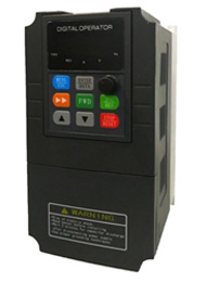
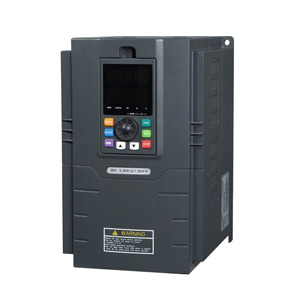
Variable frequency drive that we often talk about generally refers to the low-voltage VFD, and low-voltage VFD can be divided into single phase VFD and three phase VFD from the perspective of power supply voltage.
The biggest difference between single phase VFD and three phase VFD is that power supply of single phase VFD is consisted of a live wire and a neutral wire with a voltage of 220V. There’s only one live wire, so it’s called single phase. Power supply of the three phase VFD has three live wires, so it’s called three phase VFD, as well as three phase power input VFD.
The biggest difference between single phase VFD and three phase VFD is that power supply of single phase VFD is consisted of a live wire and a neutral wire with a voltage of 220V. There’s only one live wire, so it’s called single phase. Power supply of the three phase VFD has three live wires, so it’s called three phase VFD, as well as three phase power input VFD.
Variable frequency drive output frequency is controlled by frequency given signal, the so-called VFD frequency given mode refers to specific methods controlling the VFD output frequency. Common variable frequency drive frequency given modes include...
Generally, the variable frequency drive shows OC fault at current trip. There are several reasons for over-current: VFD module damages, so it shows fault as soon as it turns on, bad module, unbalanced output voltage, rapid increase of load current. Failed load torque lifting, or incorrect setting of acceleration and deceleration time, torque mutation, resulting in current rising. The motor capacity does not match the power of VFD. Generally, the motor power is large while the VFD power is too small.
As the output voltage of VFD belongs to the high voltage pulse train, its frequency equals to the carrier frequency and the peak equals to DC circuit voltage (513V). When the connection line between the variable frequency drive and motor is too long, the effect of wire distributed inductance and capacitance between wires can not be neglected. When the distance between motor and VFD is long, the distributed capacitance between wires and leakage inductance of motor may be close to resonance point, thus leading to high input voltage of motor and damaging the motor, or vibration during operation.
 Variable frequency drive (VFD) is an adjustable speed drive used for motor drive system, control the speed and torque of the AC motor by changing the electromechanical input frequency and voltage. Also termed variable speed drive, AC drive or frequency inverter. The VFD is a device that converts an industrial frequency power supply (50 Hz or 60 Hz) into an AC power source with various frequencies to realize varying speed operation of the motor.
VFD control circuit completes the control of the main circuit, the rectifier circuit converts the alternating current into direct current, and the direct current intermediate circuit smoothes the output of the rectifier circuit, and the inverter circuit reverses the direct current into alternating current. The VFD achieves the purpose of speed regulation by changing the power supply frequency of the stator winding of the motor.
Through variable frequency drive speed control, corresponding torque limit can be set to protect the machinery from damage, so as to ensure the continuity of process and the reliability of products. The current frequency conversion technology not only makes the torque limit adjustable, but also controls the torque accuracy to be about 3%~5%. In power frequency state, the motor can only be controlled by detecting the current value or thermal protection, but can not be operated by setting a precise torque value as in the VFD control.
In the dynamic braking method, a discharging resistance unit is added to the DC side of the VFD to consume the regenerative energy on the power resistance, thus realizing the braking. This is the most direct way to deal with regenerated energy. It consumes regenerated energy on the resistance through a special energy consumption braking circuit and converts the energy into heat energy, so it is also called “resistor braking”. It includes the braking unit and braking resistor.
According to the fluid mechanics, the flow rate Q is proportional to the rotation speed z, the pressure head H is proportional to the square of the rotation speed n, the shaft power P is proportional to the cube of rotation speed n. When the pump efficiency is constant, if the flow to be regulated decreases, the rotation speed n decreases proportionally, the shaft output power P decreases in cubic relation. Namely, the power consumption of pump motor is cubic to the rotation speed. For example, the power of a pump motor is 55 kW, when its speed drops to 4/5 of the original speed, its power consumption is 28.16 kW, corresponding power saving is 48.8%. When its speed drops to 1/2 of the original speed, its power consumption is 6. 875kW, corresponding power saving is 87. 5%.
According to the engineering experience, the VFD shall well fit with the motor power and a residual shall be reserved, so the VFD with a larger specification shall be selected. If the motor used on site needs to start and brake frequently, the brake resistance must be installed, its size shall be determined according to the power. If the equipment is required for aging testing, four quadrant products can be considered to effectively reduce power loss. If there is a separate DC current in the field, the pure inverters can be used to save investment. Moreover, a reactor must be added at the input end of high-power VFD, so as to improve the power quality of input equipment and its power factor.

Variable Frequency Drives
Featured Articles
What is a Variable Frequency Drive
 Variable frequency drive (VFD) is an adjustable speed drive used for motor drive system, control the speed and torque of the AC ...
Variable frequency drive (VFD) is an adjustable speed drive used for motor drive system, control the speed and torque of the AC ...